Microscopic Rendering
- Uttam Rao (F005FK8) and Jonah Weinbaum
Abstract
This project is concerned with examining the world of microscopic geometry - how it can be modeled and rendered. Microscopic geometric features present many problems for a renderer so we will examine some of the major problems and try to address them.
We have implemented an assortment of features in an attempt to best model these microscopic interactions including: microfacet materials, thin film materials, bump maps, and environment maps - the two latter which are included simply to increase realism in some scenes.
Motivation
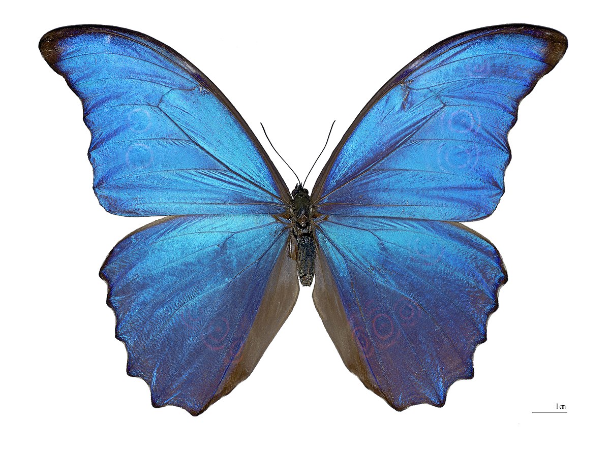
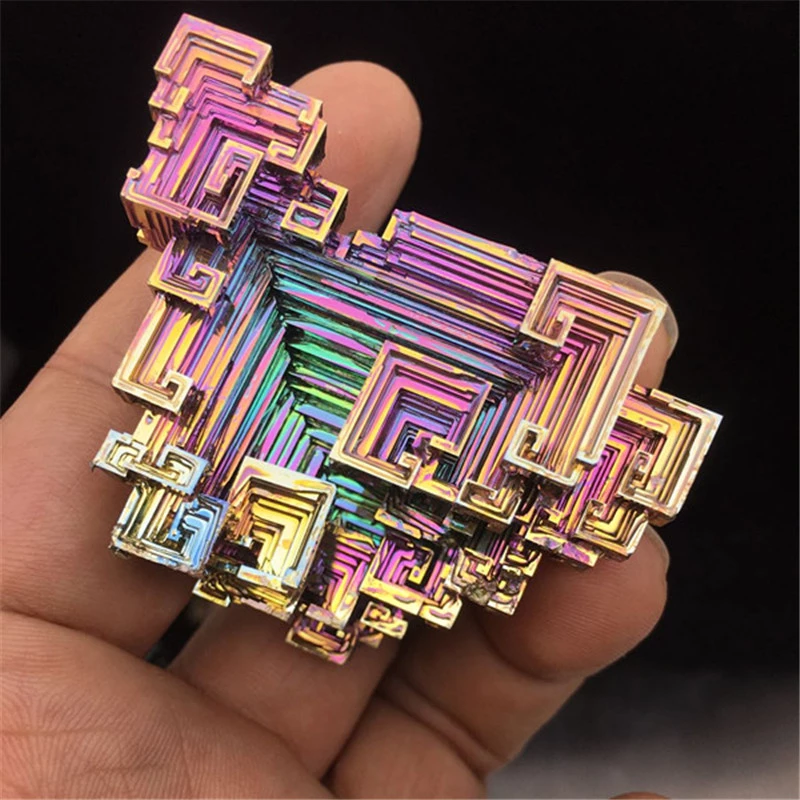
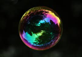
We were inspired by iridescence in nature caused by materials with surfaces small/thin enough to interfere with visible light (e.g. morpho butterflies, bismuth, soap bubbles). These nanoscale structures at the surface of the material (thin films, diffraction gratings, etc.) cause the color of every point on the surface to vary dramatically across viewing angles even though the material itself has no intrinsic color.
Below are some examples of such phenomenon:
Given that this year's theme is `Coloring Outside the Lines`, we felt that this idea fit well given that iridescence is a very rare coloring scheme found in nature and can create fantastical color schemes which seem outside the norm of the natural world. Originally we wanted to take the theme even further by having our final rendered image as several butterflies exiting a painting of a butterfly, the color literally exiting the lines of the page, but we decided to take a different approach which we will discuss shortly.
Thin Film Interference (8 Points)
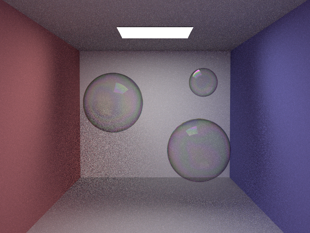
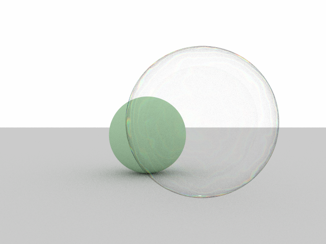
Based on a basic understanding of how thin films work from lecture, we decided to attempt rendering soapy bubbles ourselves without really looking into
any specific papers or implementations. We started with our dielectric implementation, but gave a ray two chances to reflect instead of one
(using the provided fresnel_dielectric() function). If reflected, we artificially color the surface depending on what wavelength is most constructively
produced there. Replacing the glass sphere from `04_refl` scene from Assignment 1 with our new bubble material resulted in the below image.
Although this doesn't look awful, the coloration is not acurately based on the interference of light waves. We were confident that addressing this
with a more mathematically sound backing to our code would result in a better iridescent effect.
Light interference is the key idea in rendering thin films. Waves of the same wavelength that are perfectly in phase cause exact reinforcement.
Waves which are perfectly out of phase cause cancellation. Waves that aren't exactly in phase or out phase with each other lead to results somewhere
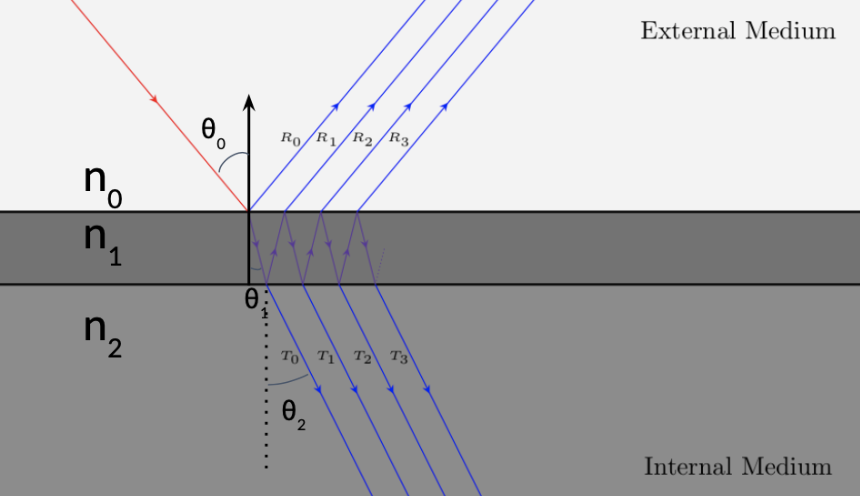
in between. In thin films, the layer(s) are so thin that a light wave may refract or reflect multiple times when interacting with them (see figure below).
The phase shift happens due to the extra distance traveled by the light wave as well as the optical phase shift when light enters a medium
with a higher refractive index.
We need to see what happens to the light as it travels through the layer and calculate the amount of light reflected.
We follow derivations given in Belcour's Paper (also in Bactrius' blogpost in a format slighty easier to read). We start with the Fresnel equations
for the transmission/reflection amplitude coefficients for `s` and `p`-polarized light going from medium `i` to `j`.

In our implementation we assume an even mix of `s`-polarized and `p`-polarized light. Considering the transmitted wave `T0` in the image above we can see that
its amplitude will be (where tau is the amplitude transmission coefficient)

since it refracts through both the top and bottom of the layer. The amplitude of `T1` will be (where rho is the amplitude reflection coefficient)

because it refracts through the top of the layer, reflects off the bottom of the layer, reflects off the top of the layer, and then refracts through
the bottom of the layer. Noticing the pattern, more generally we can say that the kth transmitted wave will have an amplitude of

Now we need to account for the phase changes that happen due to the reflections within the film and the optical path length. The phase of the kth
transmitted wave is
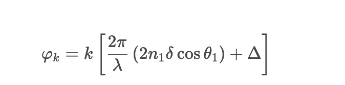
where lamba is the wavelength of the wave, lowercase delta is the thickness of the film, and uppercase delta is the sum of the pi-radian phase changes that
happen when a wave travels through the top of the layer and reflects off the bottom. Putting this all together we can calculate the transmitted intensity:

The reflected intensity is just one minus the transmitted intensity. We can use calculate this term for
red, green, and blue wavelengths to create the proper iridescent effect. Lastly we varied the thickness using perlin noise.
Microfacet Materials (4 Points)
We also found that almost all papers we had read about creating iridescent materials used a microfacet model for their base material - this is likely because the microfacet model much more accurately reflects how the surface normals are distributed and gives a much more realistic looking image which we could not seem to produce when we blended the thin-film and lambertian/specular materials.
We decided to use a GGX model since this seemed to be a common approach especially in the game rendering community. Recall that the Torrance–Sparrow BRDF has the following structure:
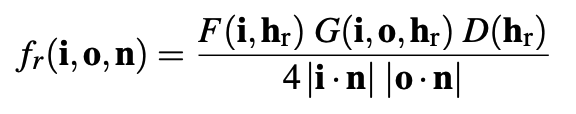
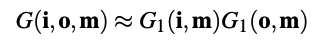
Each of these terms are evaluated according to the following equations:
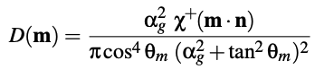
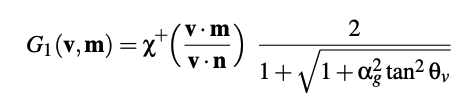
With the indicator function Chi described as follows:

And finally the original fresnel term we used was just a standard Shlick approximation as given to us in darts.
We then needed to pick a sampling method for our Monte-Carlo estimator and had read that one of the most successful sampling methods for GGX is to sample the visible distribution of normals; that is, sampling the distribution term but weighted by a visibility factor determined by the geometry terms.
To do this we used a method which sampled the projected area of a hemisphere which is equivalent to the desired distribution as explained in `A Simpler and Exact Sampling Routine for the GGX Distribution of Visible Normals`.
We then found that the associated PDF is:
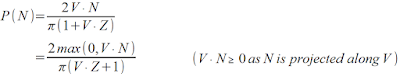
Which is then multiplied of the jacobian of reflecting a vector over a normal, since we are sampling the normal distrubtion.
```
uttamrao@Uttams-MacBook-Pro cs87-fall-2022-uttam-rao % build/darts scenes/assignment4/test_materials.json
Automatically setting number of threads in thread pool to 12.
---------------------------------------------------------------------------
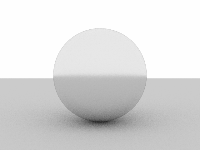
Running test for "microfacet"
Evaluating analytic PDF │████████████████████████████████████████████████████████████████████████████████████████████████████████│ (1.695s)
Integral of PDF (should be close to 1): 0.9954000014102037
Generating 32768000 samples │████████████████████████████████████████████████████████████████████████████████████████████████████│ (4.257s)
93% of the scattered directions were valid (this should be close to 100%)
Passed all 7/7 tests. Also examine the generated images.
```
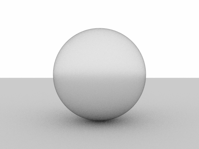
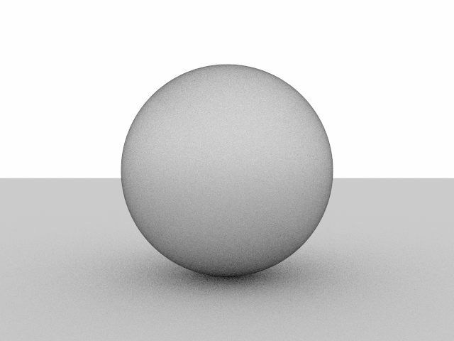
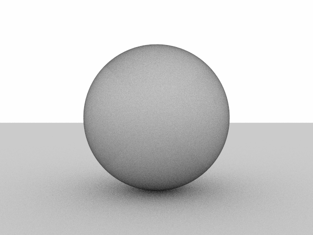
Putting all this together we were able to create conductive microfacet materials in materials/microfacet.cpp which are able to have reflections of varying degrees of roughness as follows:
A More Advanced Fresnel Term
Originally our microfacet model used a Shlick Fresnel approximation but we were able to implement a fresnel term which accounted for the change in the index-of-refraction depending on the wavelength of light coming in. Thus, setting this values for red, green, and blue, we can mimic the color of materials like gold which maintain their color through this refractive color shift.
Here are some renderings to illustrate this:
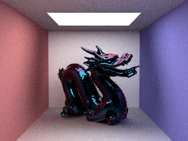
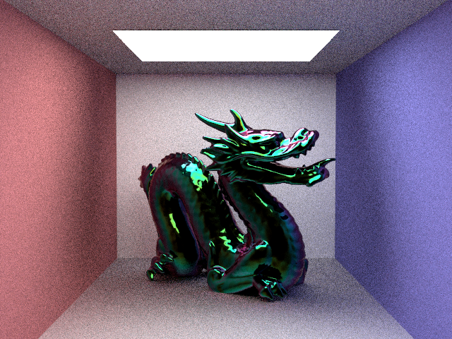
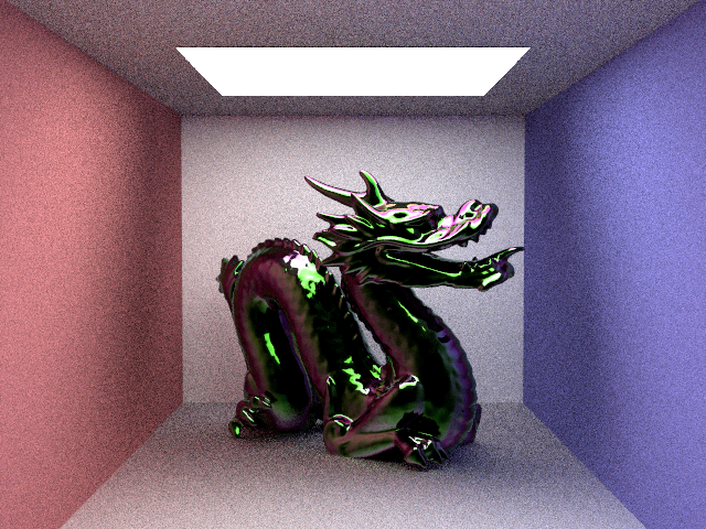
Microfacet Thin Films
Finally, we used the Fresnel term as described in the `Thin Film Interference` section to simulate a thin-film varnish on top of a microfacet material which provided realistic renderings of iridescence which the ability to simultaneously change the roughness parameter, the base index of refraction, the layers index of refraction, the layers thickness, and the albedo of the base.
Here are some renderings to illustrate this:
Bump Maps (4 Points)
We implemented bump mapping in two ways. The first is following the method described by PBRT in section 9.3.
Another way we implemented bump mapping is to convert a grayscale texture to a normal map texture. We implemented this using sobel operators
in a new image texture called textures/imagebump.cpp.
Environment Maps (2 Points)
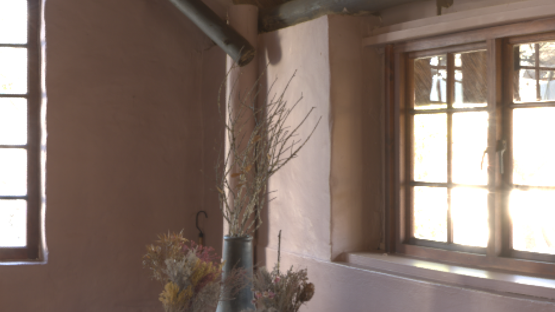
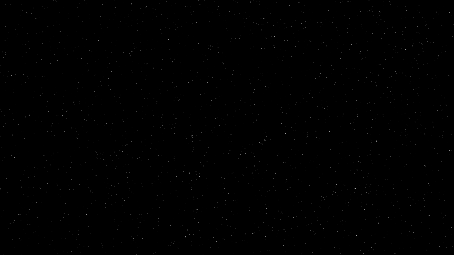
Environment mapping is relatively similar to image texturing which we have done prior. We can adapt a similar method by "texturing" the sky as if it was a sphere outside our scene which any ray that does not hit our scene will necessarily intersect. When a ray does not intersect the scene, we convert its direction to UV coordinates by first converting the spherical coordinates and then mapping these coordinates into a texture space of `[0,1]x[0,1]`. We implement this as follows in textures/envmap.cpp:
Here are some reference images in which only the environment map is rendered and serve as validation of this portions efficacy:
Final ProjectDivision of Labor
We worked together quite well as we were both quite excited about the idea of rendering such beautiful natural phenomena. We decided to split the workload as evenly as we could so the breakdown is as follows:
```
Uttam:
- Bump Mapping
- Thin Films/Iridescence
- Test Images
Jonah:
- Environment Mapping
- Microfacets
- Report
- Presentation
Both:
- Final Render
```
In reality, we spent most of our time helping each other and working together so this breakdown is not a hard or fast listing of all the ways in which we contributed.
Idea
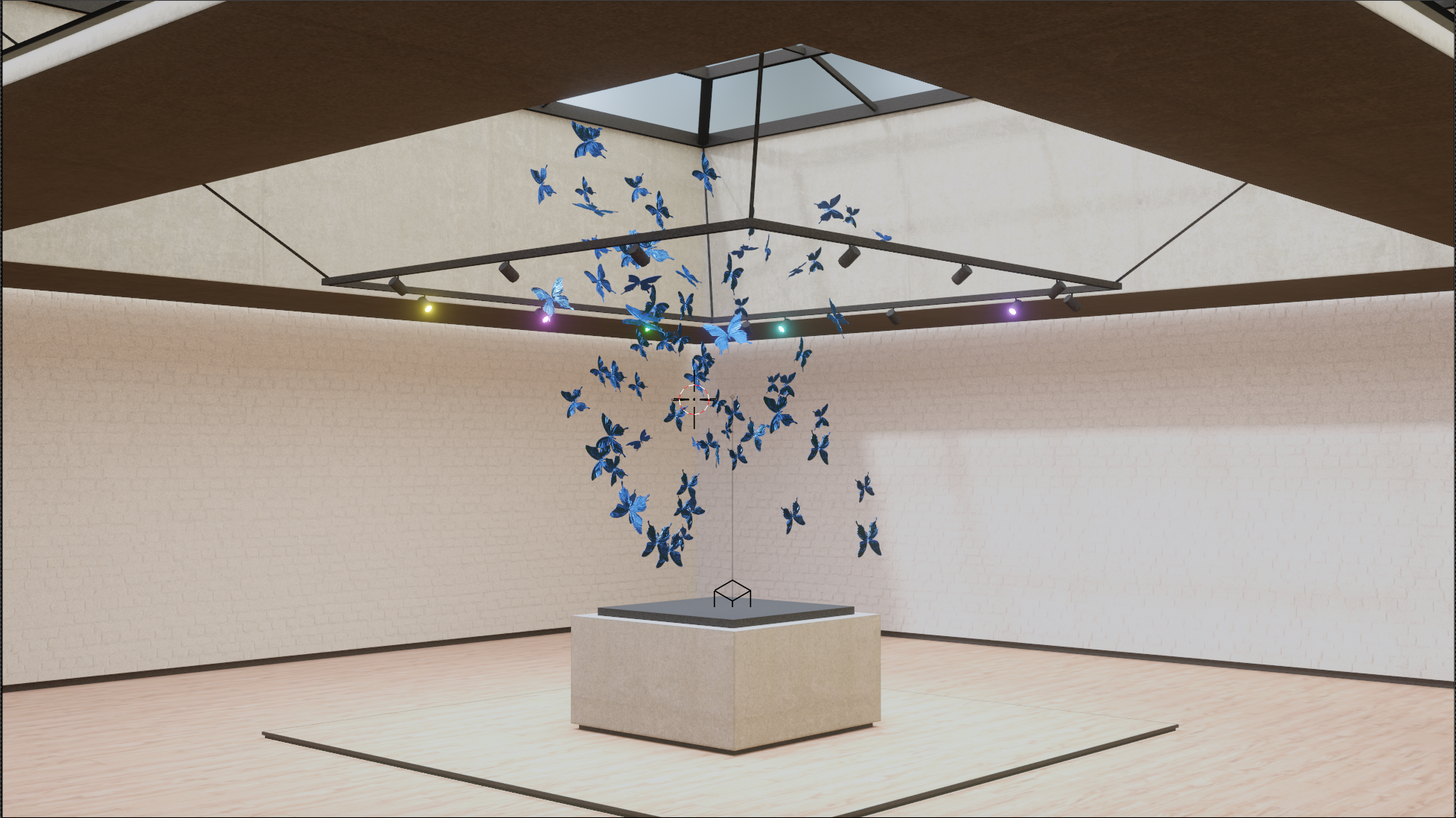
As noted, we originally intended to do a much more complicated, and frankly overzealous, scene. We decided that not only was this scene too difficult to render, but also took away from the main focus which was our implementation of iridescence. For this reason, we went back to the drawing board with the title in mind `Coloring Outside the Lines` and we decided to take our idea of rendering butterflies one step further. We wanted to create a butterfly out of butterflies, one which only appears when the viewer is viewing the scene from the right perspective. In this way, the piece itself is outside the lines of convention, deriving both the color of the butterflies from a unique source, but also the shape of the butterfly at large. In this way, the piece is not beholden to the lines surrounding the butterfly as viewing it from different angles creates a completely unique coloring and structure.
We picked a couple motivational images for reference:
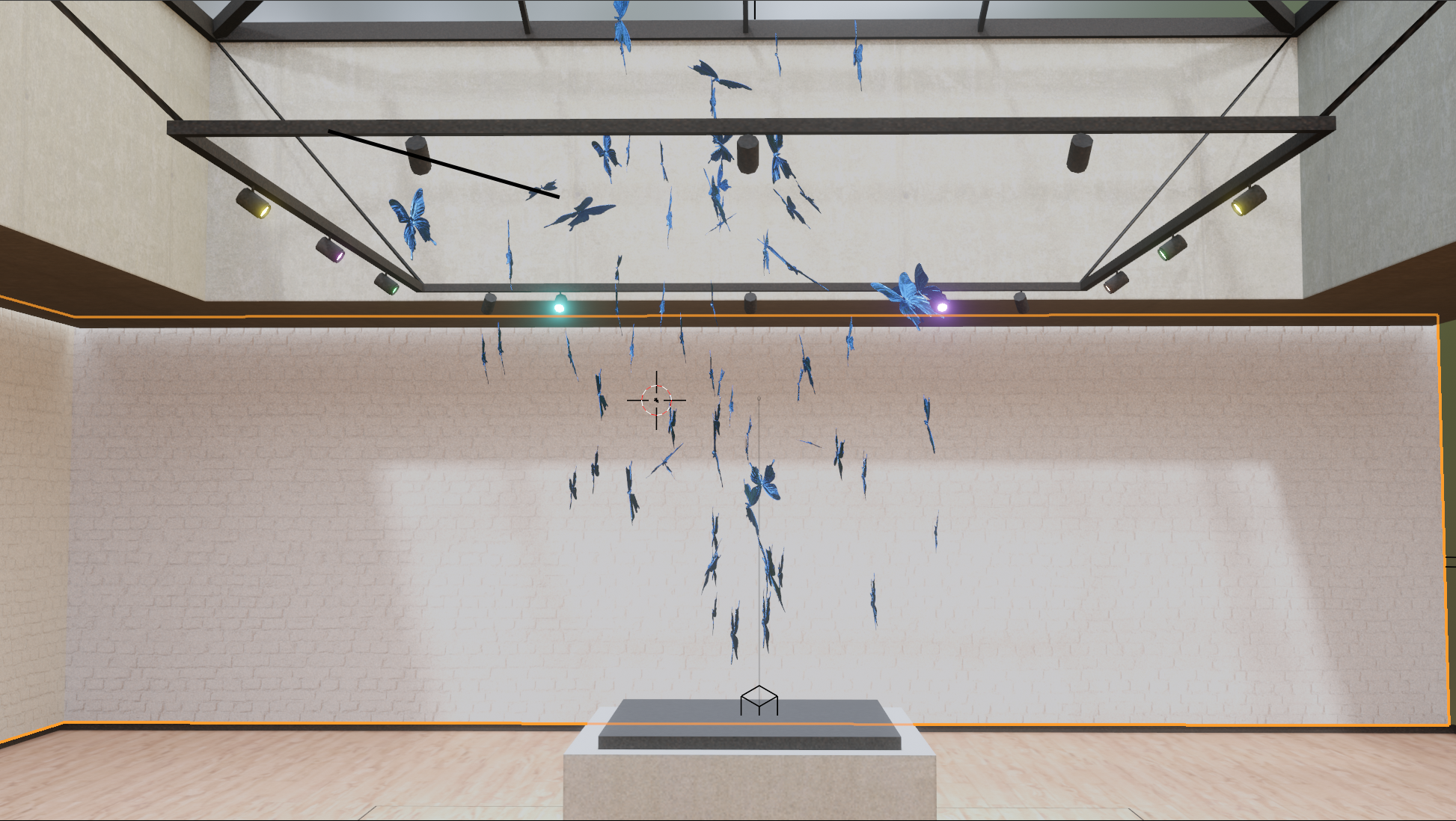
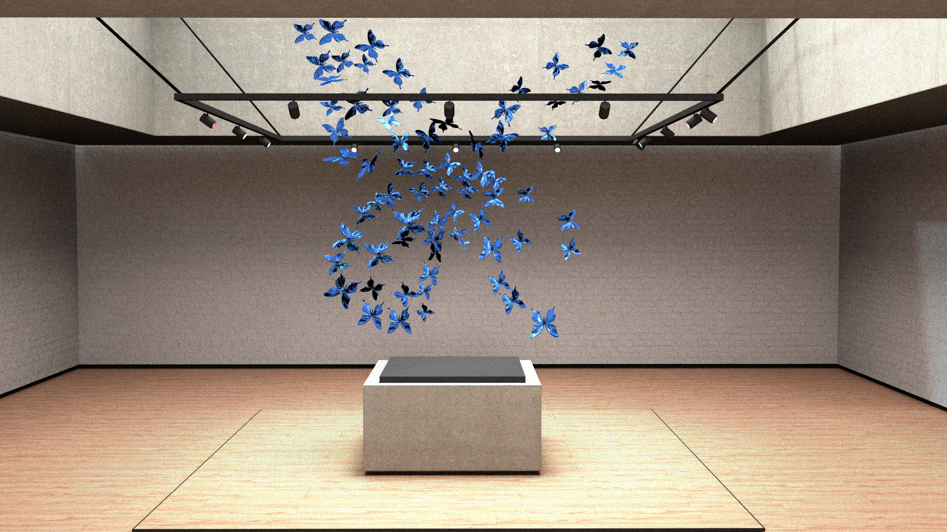
Here you can see our blender scene from alternate angles at which the butterfly structure is imperceptible:
Final Render
Works Cited
- https://www.graphics.cornell.edu/~bjw/microfacetbsdf.pdf
- https://schuttejoe.github.io/post/ggximportancesamplingpart1/
- https://jcgt.org/published/0007/04/01/
- https://hal.archives-ouvertes.fr/hal-01509746/document
- http://simonstechblog.blogspot.com/2020/01/note-on-sampling-ggx-distribution-of.html
- https://hal.archives-ouvertes.fr/hal-01518344/document
- https://en.wikipedia.org/wiki/Thin-film_interference
- https://www.gamedev.net/tutorials/programming/graphics/thin-film-interference-for-computer-graphics-r2962/
- https://hal.archives-ouvertes.fr/hal-01518344/document
- https://kwsong.github.io/cs184_final/final_report.pdf
- https://stackoverflow.com/questions/5281261/generating-a-normal-map-from-a-height-map
- https://en.wikipedia.org/wiki/Sobel_operator
Of course, this project wouldn't have been possible without the base code implemented and updated by Wojciech Jarosz, Zachary Misso, & Shaojie Jiao- A special thanks to Shaojie Jiao for aiding in debugging our final project