Part 1: Motivation
Theme
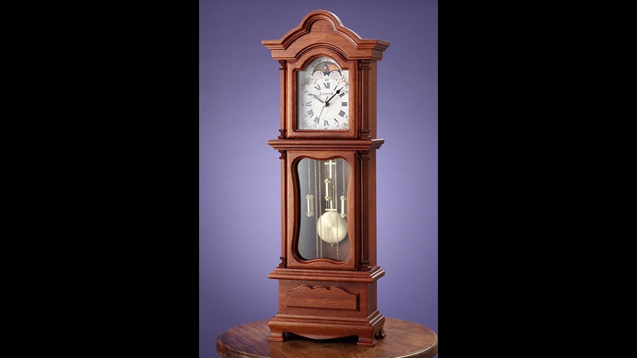
For the theme of "Something old and something new" I was planning on showing a collection of devices used to keep track of time through various ages, playing with the general theme of time.
A grandfather clock is a classic timekeeping device, and could be stationed next to a sundial,hourglass, and digital clock to achieve the effect of technology advancing to measure the same thing.
Feature 1: Anisotropic Microfacet BRDF
Feature Image

Implementation
To model metal more realistically, I decided to implement an anisotropic microfacet BRDF. This allows for the roughness in the microfacets to vary depending on the direction the surface is looked at.
The shading frame needed to be modified so that given a roughness in a specific direction there was a uniform way of applying it throughout the scene. Given an triangle in the geometry of the scene a new frame based on the UV coordinates at the points on the triangles can be created in a deterministic way. Before a random frame would be used, but now it picks specific directions based on the triangle.
A new warp function for sampling a random vector direction with a distribution based on the different roughness values of the anisotropic surface needed to be created. This required extending the warp function for the isotropic mirofacet BSDF.
Finally a new BSDF called anisotropicmicrofacet.cpp needed to be create that actually computes the light reflected at a point consistent with the functions that describe how anisotropic surfaces behave. This required extending all functions related to the isotropic mirofacet BSDF to account differences in the roughness direction.
Validation Testing
To test this I rendered an image with an anisotropic microfacet sphere and wall which have constant roughness in every direction. Thus is should look the same as an image with an isotropic microfacet sphere and wall with the same roughness. A roughness value of .1 and .9 were used for the tests.
Roughness .1 Comparison


Roughness .9 Comparison


The anisotropic microfacet agrees with the isotropic microfacet when the roughness values are the same for every direction. So implementation of the new code did not contradict the original code.
If we set the anisotropic microfacet BSDF with a high roughness value in one direction and a low roughness value in the other direction, then we should see streaks of light. We can either make horizontal stripes are vertical stripes depending on which direction we make rough.


Code coordinates
To implement the anisotropic microfacet BSDF, a new file anisotropicmicrofacet.cpp was created. Additionally modifications were made to warp.cpp (starting at line 199) and bvh.cpp (lines 518 to 541).
Part 3: Photon Mapping
Feature Image

Implementation
To model caustics more realistically, I decided to implement photon mapping. This allows for more precise measuring of light paths that ray tracing may have problems with.
Using the preprocess routine in the integrator, photons were created by emitting them from light sources and recording when they hit a diffuse surface. To prevent an infinite loop were photons kept hitting surfaces, the method used Russian roulette to terminate photons.
The various light sources needed to be moified to allow for sampling photons from the lights, as well an auxiliary functions for return the power of the light.
Validation Testing
To check if photon mapping was producing a correct image, it was first compared to a algorithm known to work. In this test it was compared to Multiple Importance Sampling.
MIS Comparison

While the caustic caused by the glass sphere appears clearer, which is the benefit of photon mapping, the image as a whole appears darker. This indicates that there is energy loss in the algorithm.
To test the that photons were being properly mapped, an image using only direct lighting was created. This image was compared to photon mapping where only direct photons were recorded, i.e. every photon was terminated on the first collision and only recorded if it hit a diffuse surface.
Direct Comparison


Since both methods should display direct lighting, they should have the same shadows. The comparison show that both methods have the same shadow cast by mirror and glass sphere.
Another method to check the photons are being properly mapped is to create a glass sphere with index of refraction 1. Computing only direct lighting will create shadows just as before. Adding in photons that first hit a dielectric surface should cause the shadow cause the glass sphere to disappear.

It appears that the shadow cast by the glass sphere is removed, although it still appears dark. I believe that the fact it is still dark is a result of the energy loss problem and not because of the photons themselves.
Code coordinates
To implementing photon mapping a new file photonmap.cpp was created. Addtionally modifications were made to emitter.h (line 123), pointLight.cpp (lines 31 to 43), and area.cpp (lines 59 to 63 and 67 to 98).
Final Image

The walls of the room and the light source were taken from cbox testing file from assigment 4.